Page copy protected against web site content infringement by Copyscape
"Learning is the only process where all small n stupid questions are more worthy than the smarter ones". Put your Queries on--www.vlsifaqs.blogspot.com or mail me at vlsihelio@gmail.com Worthy visit: www.extremephysicaldesign.blogspot.com

Think about these questions and get your answers at www.vlsifaqs.blogspot.com by this weekend.

  1. Why Setup and Hold? Or What is the reason behind there existence ?
  2. What is negative setup and why we use that?
  3. In most of the design, generally memory block has very less time margin to meet setup or hold requirements. In that case how you'll be able to meet the timing?

Note:
Thanks for your interest in making this blog more interactive. But still, very few responses.
Send your queries, asap. Mail me at vlsihelio@gmail.com or post a comment.

Don't hesitate to ask and never forget, "Learning is the only process where all small n stupid questions are more worthier than the smart ones".

Basic STA Part-3

Net and Cell Timing Arcs:

The actual path delay is the sum of net and cell delays along the timing path


Net/Interconnect Delay and Cell/Gate Delay:


Net/Interconnect Delay” refers to the total time needed to charge or discharge all the parasitics of a given net.

Total net parasitics are affected by

1. Net length

2. Net fanout


Cell/Gate delay” refers to the total time needed to reach the signal from cell input the output

Total cell delay affected by

1. Slew rate

2. Input Capacitance


Net Delay Calculation:

Prior routing stage we use Wire Load Model to estimate the delay and after routing we use the real post routed delay information for static timing analysis.

WLM is an estimation of delay, based on area and fanout. It is obsolete technology and after physical synthesis there’s no use of it.

It comes from your library or from a floorplanning tool. It is the method to initially estimate your delays and is usually overly pessimistic.


Cell Delay Calculation

Prior to Routing, cell delays are calculated from tables in the technology library. The tables are commonly indexed by input transition versus total output loading

For Example: As shown in below figure, if input transition is of 0 ns and the total output load is 0.4 fF, then the cell delay will be 6 ps.


Now you know how we do the pre-layout STA and from where we get the delay values. But can you compare it with post layout STA and why we do that?

Here few things are mentioned, I think quite enough to start thinking. Later on, we’ll discuss this in detail.


Clock Source latency and Network latency


So the Clock source latency is the delay from the oscillator to the clock pin of the chip, and the Clock network latency is the delay between the clock pin of the chip to the flop.


Slack

Slack is generally defined as the difference between the Required Times (RT) and Arrival Times (AT) at an end point.

Arrival time means actual value of time getting by tool from from level one to end of level

Required arrival time (RT) is the time before which a signal must arrive to avoid a timing violation.


STEP1: Calculate timing level for each node

STEP2: Calculate AT from level 1 to level n

Assumptions:

  1. Input arrival time of 1
  2. Wire delay 0.2, cell delay 0.5
  3. Blue colored numbers are showing levels.
  4. Green colored numbers are showing Arrival times.
  5. Red colored numbers are showing Required times.
  6. Purple colored numbers are showing respective Slacks.


Calculation of RT from level n to level 1

Assumptions:

Output required time of 2.8

Gate delay 0.5, wire delay 0.5

Calculation of Slack

Slack =RT –AT


Rectification of Violations:

There are so many methods and methodologies which are followed by the tools and the designers.

Few of them are mentioned here. Don’t predict that these all methods are followed by the designer itself, nowadays tools are smart enough to use these to meet timings.


Swapping pins:

Swap connections on cumulative pins or among equivalent nets. As you can see in the below given example, how it helps to meet timings.


Resize cell:

  1. Up size: If fan-out and Capacitance loading is more
  2. Down size: If fanout and load is less.


Buffering:

We use buffering at various stages in the whole flow, so many times,

  1. To improve the signal strength
  2. To provide delay


Cloning:

Cloning is a good method to distribute the load and to improve the signal strength.


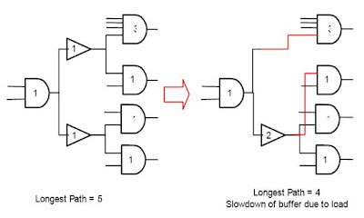
Re-design Fanout Tree:

This method is also used to meet timing, as you can see the longest path in the first design is of 5 (top most, in right side of both design, AND is of 3). But by redesigning it, we can achieve the longest path of 4.


Re-design Fan-in Tree:


Decomposition:


Requirements in the perspective of EDA tools:


Inputs & Outputs of STA

Inputs

Netlist (.v): The gate level netlist, having circuit description.

  1. Constraints (.sdc): Synopsys Design Constraint file. It contains all the timing related information about the design. Includes the Clock definition (Created clock, generated clock, Virtual clock), Uncertainty (Jitter, Skew, Extra margin), IO Delays, False paths, Multi-cycle paths, Max trans, Max fanout, Max cap, Fanout load.
  2. SDF (.sdf): Standard Delay Format File containing back-annotated delays.

OR

  1. Standard Parasitic Exchange Format (.spef): These are the parasitic of the design extracted from physical design tools.
  2. Liberty File (.lib): The delay model of every cell in the library.

Outputs

Reports: Different timing paths reports, which can be used for debugging.


Various tools used in STA

1. Prime Time (PT) - Synopsys

2. Design Time (DT) - Synopsys

3. Nano Time - Synopsys

4. Path Mill - Synopsys

5. ETS - Cadence

6. Pearl - Cadence

7. Velocity - Mentor Graphics

8. Eins Timer - IBM

9. Eins TLT - IBM

10. Motive - Viewlogic (Now owned by Synopsys)

11. Time Craft - Incentia


BASIC STA Part-2

Timing Violations:
  • Setup or Hold violation:
  1. Leads to improper operation of the flip flop and the connected components, it can result in missed data or ignored actions.
  2. The output of the flip flop goes into a state of metastability in the case of Setup/Hold violations.
  • Recovery and Removal Violations :
  1. Violations of Preset and Clear signal with respect to the Clock.


Setup Time:

  • The time required for the input data to be stable before the triggering clock edge.
  • So, Set-up check establishes that the path is fast enough for the desired clock frequency.


Hold Time:

  • The time required for the data to remain stable after the triggering clock edge.
  • So, hold check ensures that the path is not too fast so that data is not passed through.


Why Setup & Hold?

  1. Setup & Hold times are because of the intrinsic delays of the flip flop. Intrinsic delays are the actual delays of the transistors inside the cell.
  2. Setup and Hold are the times required for charging the capacitances present inside in cell.

Delay of an Inverter:

t = Rp * C

The delay is decided by the resistance of Pmos and the output capacitance.

The product ‘RC’ is called the “TIME CONSTANT”. This determines the delay of the cell.


When Vo = Logic ‘1’ t = Rn * C

The delay is decided by the resistance of Nmos and the output capacitance.


How to remove Setup & Hold violations:

To solve setup violation

1. By optimizing and restructuring the combinational logic between the flops of design. In big designs, we dont do this by ourselves, generally tool does this for us. And what are the ways that tool follows for the same? We'll discuss that in next post.


2. By using “Tweak flops” to offer less setup delay. Since, Tweak launch-flop have better slew at the clock pin and this makes CK->Q of launch flop faster, so that it helps in fixing setup violations.

3. By using Useful- skews.


To solve Hold Violations

1. By adding delay/buffer cell. Since the simple buffer offers less delay, so we use special Delay cells whose functionality remains same, i.e. Y=A, but with more delay.

2. By providing delay to the launch flop clock.

3. Where the hold time requirement is huge, we can use Lock-up Latches also.


Few GOOGLIES for you:
  1. What is negative setup? And where we use that?
  2. In most of the design, generally memory block has very less time margin to meet setup or hold requirements. In that case how you'll be able to meet the timing?
Note: For more faqs, keep visiting http://vlsifaqs.blogspot.com

STA: Critical terms

  1. Critical path: The path between an input and an output with the maximum delay.
  2. Recovery time: It is the minimum time that an asynchronous control must be stable before the clock active-edge transition.
  3. Removal time: It is the minimum length of time that an asynchronous control must be stable after the clock active-edge transition.


Jitter : Variation in period from clock source (PLL)


Insertion Delay

  • The delay between the clock root pin and clock sink pin of the flip flop


Glitch- A glitch is a short-lived fault in a system.

  • An electrical pulse of short duration that is usually the result of a fault or design error, particularly in a digital circuit

Input Delay:


Output Delay:


Single Cycle Paths:

  • By default, static timing tools assume all timing paths to be single cycle paths


There could be exceptions defined to the above behavior:

  1. Multi-cycle paths
  2. False paths


Multi-Cycle Paths:

  • Those paths that require more than one clock period for execution are called as multi-cycle paths.
  • It’s essential that multi-cycle paths in the design be identified both for synthesis and STA.


False Paths:

  • A path that can never be sensitized in the actual circuit
  • These paths are those that are logically/functionally impossible
  • The goal in static timing analysis is to do timing analysis on all “true” timing paths, these paths are excluded from timing analysis.


Combinational Loop:


  • Most STA’s can’t leave combinational loops in the design, because a race condition will occur.
GOOD ONE:
If i am not defining the False or Multicycle paths or Combinational Loops or Input/Output Delay in my constraint file (.sdc). In that case, what can be the effects you will find in your reports? (Analyze this one by one.)

Note: For more faqs, keep visiting http://vlsifaqs.blogspot.com

Clock skews (timing skew):

  • Clock signal in synchronous circuits arrives at different components at different times.


Clock skew = clock insertion delay of FF1 - clock insertion delay of FF2

Reasons for the Skew:

  1. Wire-interconnect length
  2. Temperature variations
  3. Variation in intermediate devices
  4. Capacitive coupling
  5. Material imperfections


Two Types of Clock Skew:

  1. Negative skew
  2. Positive skew

Positive skew:

  • Occurs when the clock reaches the receiving register later than it reaches the register sending data to the receiving register.

Negative skew:

  • Is the opposite:- the receiving register gets the clock earlier than the sending register.

BASIC STA Part-1

Timing Analysis:

Timing analysis is necessary to calculate the design’s system performance, describes the chips specification, accounts for chip pad loading, helps in achieving clock speed and above all of the reasons, determines if the chip works in two contrast places, like Sahara and Switzerland.


Types of timing analysis:

1. Dynamic timing analysis (DTA)

2. Static timing analysis (STA)

Dynamic Timing Analysis (Gate level Simulation):

A series of vectors over a time are applied during a simulation run, simulation calculates the logic value and delays over that time. So, in that manner we check the design’s functionality with time.


Static Timing Analysis:

Static timing analysis is a method for determining if a circuit meets timing constraints without having to simulate.

So, it validates the design for desired frequency of operation, without checking the functionality of the design.


Comparison of Analysis

Dynamic timing

  1. Requires exhaust set of vectors
  2. Checks for both functional and timing problems
  3. Requires more resources like run time, CPU memory, etc.
  4. Can work with any type of Logic either synchronous or asynchronous
  5. Slower as compared to STA.
  6. Easy to learn

Static timing

  1. Doesn't requires any set of vectors.
  2. Checks for timing only.
  3. Requires fewer resources than DTA.
  4. Restricted to synchronous part of the design only.
  5. Faster as compared to DTA.
  6. Difficult to learn


Why Static timing Analysis?

  1. To analyze the timing relationships of a given circuit to verify that the circuit works at the specified frequency (verification).
  2. 100 % path coverage is possible because no design specific pattern is required.
  3. You can’t achieve the clock speed without it.
  4. All paths are assumed critical.
  5. Process variation across die can be modeled.
  6. Constraints and reports are concise and easy to interpret.
  7. It can detect other serious problems like glitches, slow paths and clock skew.

Note: This analysis is done to provide the engineer feedback in order to help modify the design and/or modify the constraints to improve the timing quality of the design.


Place of STA in the ASIC Flow


STA involves three main steps:

  1. Design is broken down into sets of timing paths.
  2. Delay of each path is calculated.
  3. Path delays are checked to see if timing constraints have been met.

But first some Basic STA concepts:

Timing Paths:


Each path has a startpoint and an endpoint

  1. Startpoints:

Input ports (A, Q)

Clock pins of sequential devices (CLk)

  1. Endpoints:

Output ports (D, Z)

Data input pins of sequential devices (D)


Basic Timing Paths

Generally recognizes five types of default timing paths:

  1. Clock to setup
  2. Clock to pad
  3. Pad to pad
  4. Pad to set up

Clock to setup:

A clock to setup path starts at flip flop clock inputs, propagates through the flip flop Q out put and any number of levels of combinational logic, and ends at non clock flip flop register inputs.


Clock to pad:

It starts at a clock input of a flip-flop, propagates through the flip-flop Q output and any number of levels of combinational logic, and ends at an output pad.

Pad to Pad :

A pad to pad path starts at an input of the chip, propagates through one or more levels of combinational logic, and end at an output pad of the chip.


Pad to Setup:

A pad to setup path starts at an input pad of chip and ends at flip flop input.